- Have any questions?
- +86 15953537010
- admin@wepower-electronic.com
- Home
- Pressure Measurement
- Diaphram Pressure Transmitter
- Remote Seal Capillary Level Transmitter
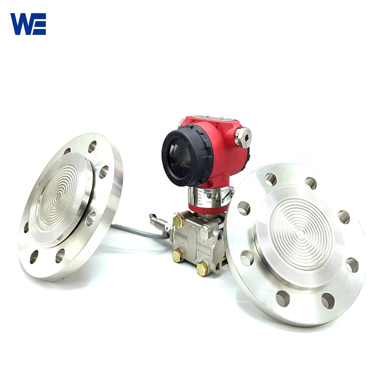
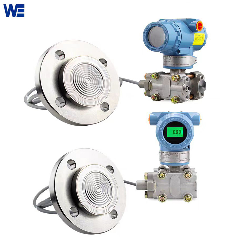
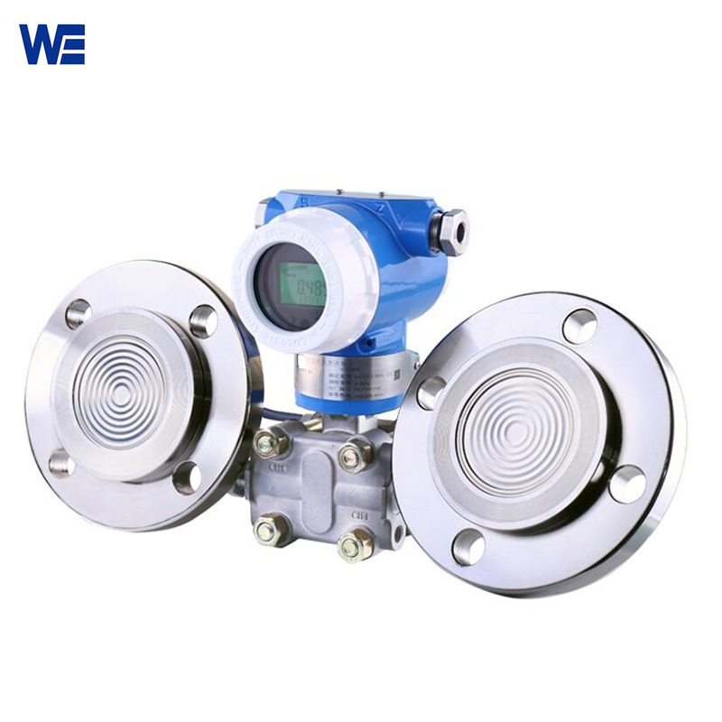
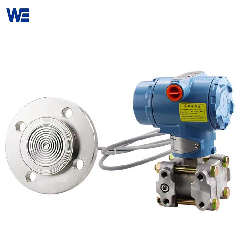
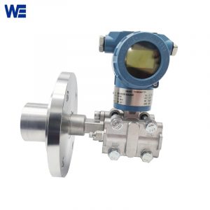
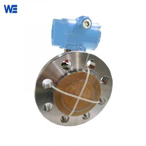
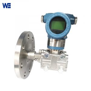
Remote Seal Capillary Level Transmitter
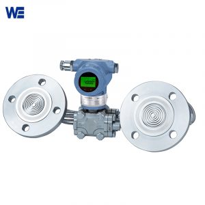
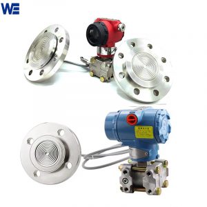
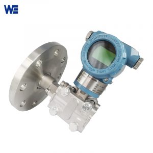
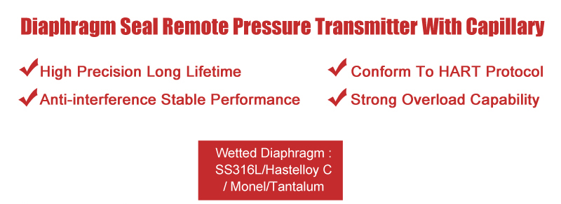
Both the differential pressure and the level can be measure of the tanks with 4-20mA output .The wetted diaphragm materials of the remote seal capillary level transmitter are SS316L, Hastelloy C-276, Monel, tantalum, etc., which can be applied to the anti-corrosion requirements of different situations.
![]()
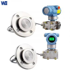
Remote Seal Capillary Level Transmitter is mainly used for measurement in the following occasions: viscous medium at high temperature, easy to crystallize medium, precipitation medium with solid particles or suspended matter, strong corrosive or highly toxic medium,the continuous accurate measurement interface and the density .Remote transmission device can avoid the mixing of different instantaneous media, so that the measurement results truly reflect the actual situation of the process change. Remote seal capillary level transmitter can be measure both the differential pressure and the level of the tanks with 4-20mA output .
As the isolation diaphragm is very thin, it is a weak link in corrosion resistance, so the wetted diaphragm material Hastelloy C-276, Monel, tantalum, etc., which can be applied to the anti-corrosion requirements of different situations.
![]()
What is the measuring principle of the double flange remote capillary level transmtter ?
The measuring principle of the double flange remote level transmitter is that when the two pressures of the measured medium pass into the high and low pressure chambers, they act on the isolation diaphragms on both sides of the sensitive element through the isolation sheet and The filling liquid in the element is transferred to both sides of the measuring diaphragm. The liquid level transmitter is composed of a measuring diaphragm and the electrodes on the insulating plates on both sides each constitute a capacitor. When the pressure on both sides is not constant, the measurement diaphragm will be displaced, and its displacement is proportional to the pressure difference. Therefore, the capacitance on both sides is not equal. Through the oscillation and demodulation link, it is converted into a signal proportional to the pressure.
When one end of the differential pressure gauge is connected to the liquid phase and the other end to the gas phase, according to the principle of hydrostatics, there are:
PB=PA+Hρg (2-1) ,In the formula:
H—— liquid height;
Ρ——The density of the measured medium;
G——The acceleration of gravity of the measured local area.
From formula (2-1), we can get:
ΔP= PB-PA= Hρg
In general, the density and gravitational acceleration of the measured medium are known. Therefore, the differential pressure measured by the differential pressure gauge is proportional to the height H of the liquid.
![]()
| Process Fluid : | Liquid, Gas or Vapor |
| Application: | Liquid Level, Differential Pressure |
| Material | Flange : Carbon steel/ Stainless Steel 304/ Stainless Steel 316 |
| Diaphragms : Stainless Steel 316L/ Hastelloy B/ Hastelloy C/ Tantalum/ PTFE-coated Tantalum Diaphragm | |
| Capillary : Stainless Steel with PVC coating | |
| Flange Size | 40mm, 50mm, 80mm, 100mm, 1-1/2″, 2″, 3″, 4″ |
| Flange Rating | JIS 10K / JIS 20K / JIS 40K |
| ANSI 150# / ANSI 300# / ANSI 600# | |
| DIN PN10 / PN16 / PN25 / PN40 | |
| Tri Clamp (DIN32676 / ISO2852) | |
| Installation Style | Direct-mount: RD/ One-sided Capillary: RD1/ Two-sided Capillaries: RD2 |
| Capillary Length | 1.0 M ~ 10 M |
| Time Response | Less than 1.12 seconds |
| Accuracy | +/-0.15% of Span |
| Explosion-proof | EX d; Ex ia |
| Fill Fluid and Maximum : | Silicone (Max. Temperature 130 °C) |
| Max. Temperature | Direct-Mount : -20 to 80 °C |
| Remote Diaphragm : -40 to 280 °C | |
| Max. Pressure | 8.0MPa |
| Stability | +/-0.15% of URL for 2 years |
![]()

![]()
![]()
![]()
![]()
| WE3051RD Series | ||||||||||
| Example: WERD2-A22B4-N05-W | ||||||||||
| WERD | X- | X | X | X | X | X | -X | XX | -X | Description |
| Installation Style | RD- | / | Direct-mount | |||||||
| 1- | One-sided Capillary Connects Remote Diaphragm Seal | |||||||||
| 2- | Two-sided Capillaries Connect Remote Diaphragm Seal (RD2 Only) | |||||||||
| Process Connection | 1 | / | PN10 | |||||||
| 2 | PN16 | |||||||||
| 3 | PN25 | |||||||||
| 4 | PN40 | |||||||||
| A | ANSI 150# | |||||||||
| B | ANSI 300# | |||||||||
| J | JIS 10K | |||||||||
| K | JIS 20K | |||||||||
| L | JIS 40K | |||||||||
| T | Tri-clamp (DIN32676 / ISO2852) | |||||||||
| Z | Other | |||||||||
| Flange Size | 1 | / | 1-1/2″ (Diaphragm Diameter If Extended: 38mm) | |||||||
| 2 | 2″ (Diaphragm Diameter If Extended: 48mm) | |||||||||
| 3 | 3″ (Diaphragm Diameter If Extended: 66mm) | |||||||||
| 4 | 4″ (Diaphragm Diameter If Extended: 89mm) | |||||||||
| Diaphragm Extension Length | 0 | / | Flush Diaphragm | |||||||
| 2 | 2″ (50mm) | |||||||||
| 4 | 4″ (100mm) | |||||||||
| 6 | 6″ (150mm) | |||||||||
| Diaphragm Material | N | / | Stainless Steel 316L | |||||||
| B | Hastelloy B | |||||||||
| C | Hastelloy C | |||||||||
| T | Tantalum | |||||||||
| P | PTFE-coated Tantalum Diaphragm (PTFE Thickness:40μm) | |||||||||
| Z | Other | |||||||||
| Flange Material | N | / | Carbon Steel | |||||||
| 4 | Stainless Steel 304 | |||||||||
| 6 | Stainless Steel 316 | |||||||||
| Z | Other | |||||||||
| Fill Fluid | -N | / | Silicone (Max. Temperature 130 °C) | |||||||
| -S | HT Silicone (Max. Temperature 280 °C) | |||||||||
| -F | Fluorine (Max. Temperature 160 °C) | |||||||||
| -V | Vegetable Oil (Max. Temperature 130 °C) | |||||||||
| Capillary Length | NN | / | Direct-Mount | |||||||
| 01-10 | 1 M ~ 10 M | |||||||||
| Option | – N | None | ||||||||
| – W | Oil-free and Water-free Treatment | |||||||||

